Serial Module Configuration
The serial module lets you talk to and control your Meshtastic device over a UART serial port. Set the mode to match your use-case — from plain text bridging to raw binary tunnels, NMEA output, and packet logging.

Serial Module Config Values
Enabled
Enables the serial module.
Echo
If set, any packets you send will be echoed back to your device. Useful for confirming transmissions in TEXTMSG mode.
Mode
Defaults to SIMPLE.
| Mode | Description |
|---|---|
DEFAULT | Alias for SIMPLE. |
SIMPLE | Raw binary pass-through. Bytes in are sent as a mesh packet on a channel named serial; received packets are written back as raw bytes. |
PROTO | Exposes the Meshtastic Protobuf Client API on the serial port — the same protocol used by phone apps and the Python CLI. Produces no human-readable output; use meshtastic --port <FTDI_PORT> --listen to observe the stream. |
TEXTMSG | Any string sent to the serial port is broadcast as a text message on the default channel. Received messages are printed as <ShortName>: <text>. |
NMEA | Outputs NMEA 0183 sentences every 2 seconds: one $GNGGA sentence for the device's own position, plus $GPWPL sentences for each mesh node with a valid position. |
CALTOPO | Sends NMEA $GPWPL Waypoint sentences every 10 seconds for all nodes with valid positions, for use with CalTopo / SARTopo. |
WS85 | Parses wind speed data from an Ecowitt WS85 connected over serial and transmits telemetry every 5 minutes. Requires hardware modification of the WS85. |
VE_DIRECT | Receives the VE.Direct protocol from Victron Energy products. |
MS_CONFIG | Configures and views parameters of MeshSolar. |
LOG | Outputs a formatted log line for every packet sent or received by the node, including text, telemetry, and position packets. |
LOGTEXT | Logs only text packets (channel messages and direct messages) sent or received by the node. |
Receive GPIO Pin
The GPIO pin connected to the RX line of your serial adapter.
On the RAK4631 with the RAK19007 or some RAK19003 baseboards, use TXD1 (16) and RXD1 (15). Set GPS Mode to Not_Present for this combination. On other RAK19003 variants, use TXD0 (20) and RXD0 (19).
Transmit GPIO Pin
The GPIO pin connected to the TX line of your serial adapter. Always cross-connect: device TX → adapter RX, and device RX → adapter TX.
Baud Rate
The serial baud rate. BAUD_DEFAULT is 38400.
Timeout
How long the module waits after the last received byte before treating the accumulated data as a complete packet. Only relevant in SIMPLE mode. Default (0) corresponds to 250 ms.
Override Console Serial Port
When enabled, redirects the primary USB serial port to serial module output instead of the debug console. Only valid with NMEA and CALTOPO modes — using it with any other mode will produce a configuration error and the module will not start. Has no effect if TX/RX GPIO pins are also configured (pogo-pin output takes precedence).
Serial Module Config Client Availability
- Android
- Apple
- CLI
- Web
Android
Serial Module Config options are available for Android.
- Open the Meshtastic App
- Navigate to: Settings > Serial
Apple
All serial module config options are available on iOS, iPadOS and macOS at Settings > Module Configuration > Serial.
CLI
All serial module config options are available in the Python CLI. Chaining multiple --set flags in one command is recommended — the device reboots after each write.
| Setting | Acceptable Values | Default |
|---|---|---|
| serial.enabled | true, false | false |
| serial.echo | true, false | false |
| serial.mode | DEFAULT SIMPLE PROTO TEXTMSG NMEA CALTOPO WS85 VE_DIRECT MS_CONFIG 9 (LOG) 10 (LOGTEXT) | DEFAULT |
| serial.rxd | GPIO Pin Number 1-39 | Default of 0 is Unset |
| serial.txd | GPIO Pin Number 1-33 | Default of 0 is Unset |
| serial.baud | BAUD_DEFAULT BAUD_110 BAUD_300 BAUD_600 BAUD_1200 BAUD_2400 BAUD_4800 BAUD_9600 BAUD_19200 BAUD_38400 BAUD_57600 BAUD_115200 BAUD_230400 BAUD_460800 BAUD_576000 BAUD_921600 | BAUD_DEFAULT (38400) |
| serial.timeout | integer (milliseconds) | Default of 0 corresponds to 250 ms |
| serial.override_console_serial_port | true, false | false |
meshtastic --set serial.enabled true
meshtastic --set serial.enabled false
meshtastic --set serial.echo true
meshtastic --set serial.echo false
meshtastic --set serial.mode TEXTMSG
meshtastic --set serial.mode NMEA
meshtastic --set serial.rxd 7
meshtastic --set serial.txd 28
meshtastic --set serial.baud BAUD_DEFAULT
meshtastic --set serial.baud BAUD_115200
meshtastic --set serial.timeout 15
Web
All serial module config options are available in the Web UI.
SenseCAP T1000-E Serial Setup
The SenseCAP Card Tracker T1000-E is a credit-card-sized Meshtastic tracker running a Nordic nRF52840. It supports the serial module via two connection methods.
Pogo Pin Connection (TEXTMSG, SIMPLE, LOG, LOGTEXT modes)
The T1000-E exposes its debug UART (Serial2) on the four pogo pins at the bottom edge of the device. Connect a USB-to-UART adapter (FTDI FT232, CP2102, CH340, or similar — 3.3 V logic level) using the following wiring:
| T1000-E Pogo Pin | USB-UART Adapter |
|---|---|
| GND | GND |
| TX (P0.16) | RX |
| RX (P0.17) | TX |
| 3V3 | (do not connect — device is self-powered) |
Use a 3.3 V logic-level adapter. A 5 V adapter will damage the nRF52840.
Once wired, configure the module using the T1000-E's USB CDC port (the magnetic charging cable):
meshtastic --port <USB_PORT> \
  --set serial.enabled true \
  --set serial.txd 16 \
  --set serial.rxd 17 \
  --set serial.mode TEXTMSG \
  --set serial.baud BAUD_DEFAULT
After the device reboots, open the FTDI adapter port at 38400 8N1 to send and receive messages.
USB-Direct Connection (NMEA and CalTopo modes only)
For NMEA and CalTopo output modes, the T1000-E can stream data over its built-in USB CDC port without any extra hardware:
meshtastic --port <USB_PORT> \
  --set serial.enabled true \
  --set serial.override_console_serial_port true \
  --set serial.mode NMEA
After the device reboots, open the same USB port at 38400 8N1 to receive NMEA sentences.
Finding Your Serial Port
- macOS
- Windows
- Linux
USB CDC port (magnetic charging cable):
ls /dev/cu.usbmodem*
# Example output: /dev/cu.usbmodem0000001
FTDI / CP2102 pogo-pin adapter:
ls /dev/cu.usbserial-* /dev/cu.SLAB_USBtoUART 2>/dev/null
# Example output: /dev/cu.usbserial-A10KMFPL
Open Device Manager → Ports (COM & LPT).
- The T1000-E USB CDC port appears as USB Serial Device (COMx).
- An FTDI or CP2102 pogo-pin adapter appears as USB Serial Port (COMx) after its driver is installed.
Install the CP210x driver for Silicon Labs adapters or the FTDI VCP driver for FTDI adapters if the port does not appear.
You can also list ports with Python:
python -m serial.tools.list_ports --verbose
USB CDC port:
ls /dev/ttyACM*
# Example output: /dev/ttyACM0
FTDI / CP2102 pogo-pin adapter:
ls /dev/ttyUSB*
# Example output: /dev/ttyUSB0
If you get a Permission denied error, add your user to the dialout group and log out/in:
sudo usermod -a -G dialout $USER
Mode Examples
TEXTMSG — Send and Receive Text Messages
TEXTMSG mode bridges the serial port to the Meshtastic text message channel. Any string sent to the serial port is broadcast as a text message; any received text message is printed as <ShortName>: <message>.
Step 1 — Configure the T1000-E:
meshtastic --port <USB_PORT> \
  --set serial.enabled true \
  --set serial.txd 16 \
  --set serial.rxd 17 \
  --set serial.mode TEXTMSG \
  --set serial.baud BAUD_DEFAULT
Step 2 — Open the pogo-pin UART (<FTDI_PORT>) at 38400 8N1:
- macOS
- Windows
- Linux
brew install tio
tio -b 38400 -e <FTDI_PORT>
screen <FTDI_PORT> 38400
# Exit with Ctrl-A, then k, then y
Use PuTTY → Connection type: Serial → Speed: 38400 → Serial line: COM3 → Open.
Or with Python pyserial:
pip install pyserial
python -m serial.tools.miniterm <FTDI_PORT> 38400
sudo apt install tio
tio -b 38400 -e <FTDI_PORT>
sudo apt install minicom
minicom -b 38400 -D <FTDI_PORT>
# Exit with Ctrl-A, then x
Step 3 — Type a message and press Enter. It is broadcast over the mesh. Incoming messages appear as:
CALLSIGN: Hello from the mesh!
Enable echo to confirm your own transmissions: meshtastic --port <USB_PORT> --set serial.echo true
SIMPLE — Transparent UART Tunnel
SIMPLE mode is a raw binary pass-through. Bytes written to the serial port are sent as a mesh packet on a channel named serial; received packets on that channel are written as raw bytes back to the serial port.
A channel named serial must exist on the device. Create one with:
meshtastic --port <USB_PORT> --ch-add serial
meshtastic --port <USB_PORT> \
  --set serial.enabled true \
  --set serial.txd 16 \
  --set serial.rxd 17 \
  --set serial.mode SIMPLE \
  --set serial.baud BAUD_DEFAULT \
  --set serial.timeout 250
Connect at 38400 8N1 and send up to 237 bytes per packet. The module frames a packet by detecting a gap of serial.timeout milliseconds in the byte stream (default 250 ms).
PROTO — Protobuf Client API
PROTO mode exposes the full Meshtastic Protobuf Client API on the serial port — the same protocol used by phone apps and the Python CLI. It produces no human-readable output.
meshtastic --port <USB_PORT> \
  --set serial.enabled true \
  --set serial.txd 16 \
  --set serial.rxd 17 \
  --set serial.mode PROTO
meshtastic --port <FTDI_PORT> --listen
For embedded integration, use the Meshtastic Arduino client library.
NMEA — GPS Position Stream (USB or Pogo Pins)
NMEA mode outputs NMEA 0183 sentences every 2 seconds: a $GNGGA sentence for the device's own position, plus $GPWPL sentences for each mesh node with a valid position. Position is zero until the device acquires a GNSS fix.
Option A — USB direct (recommended for T1000-E):
meshtastic --port <USB_PORT> \
  --set serial.enabled true \
  --set serial.override_console_serial_port true \
  --set serial.mode NMEA \
  --set serial.baud BAUD_DEFAULT
After the device reboots, open <USB_PORT> at 38400 8N1 to read the stream.
On macOS with the T1000-E, after the device reboots into NMEA override mode the USB CDC port (/dev/cu.usbmodem*) may drop and not automatically re-appear. If the port disappears, unplug and replug the magnetic charging cable and the port will re-enumerate. This is a known nRF52840 USB CDC behavior.
Option B — Via pogo pins:
meshtastic --port <USB_PORT> \
  --set serial.enabled true \
  --set serial.txd 16 \
  --set serial.rxd 17 \
  --set serial.mode NMEA \
  --set serial.baud BAUD_DEFAULT
Reading NMEA output:
- macOS
- Windows
- Linux
Open PuTTY at 38400 8N1 on the port to view raw sentences. To feed into navigation software, use a virtual COM port splitter such as com0com or configure the software to read directly from the COM port.
Example output:
$GNGGA,232843.00,4761.234,N,12208.123,W,1,08,1.2,88.0,M,,,, *XX
$GPWPL,4761.234,N,12208.123,W,NODENAME*XX
cat <PORT>
To feed into gpsd:
sudo gpsd -N -n <PORT>
cgps -s
CALTOPO — Search and Rescue Mapping
CALTOPO mode sends NMEA $GPWPL Waypoint sentences every 10 seconds for all nodes in the mesh with a valid position. Designed for CalTopo / SARTopo to display mesh nodes on a rescue map in real time.
meshtastic --port <USB_PORT> \
  --set serial.enabled true \
  --set serial.override_console_serial_port true \
  --set serial.mode CALTOPO \
  --set serial.baud BAUD_DEFAULT
After applying this config the T1000-E reboots. On macOS the port may disappear — unplug and replug the magnetic charging cable to bring it back.
Open <USB_PORT> in CalTopo's GPS input at 38400 8N1. Each node with a position appears as a waypoint, refreshed every 10 seconds.
LOG — Mesh Packet Activity Logger
LOG mode outputs a formatted log line for every packet the node sends or receives — text, telemetry, position, and more. Ideal for logging mesh activity to a data logger such as a SparkFun OpenLog connected to the T1000-E pogo pins.
meshtastic --port <USB_PORT> \
  --set serial.enabled true \
  --set serial.txd 16 \
  --set serial.rxd 17 \
  --set serial.mode LOG \
  --set serial.baud BAUD_DEFAULT
If your CLI reports that LOG is not a valid enum value, use the numeric form instead: --set serial.mode 9. This occurs with CLI versions older than 2.7.10.
Open the FTDI port at 38400 8N1 to watch the stream. Example output:
[TX] TEXT  ch=0  from=!deadbeef  to=!ffffffff  "Hello mesh!"
[RX] POSN  ch=0  from=!cafebabe  to=!ffffffff  lat=47.6062 lon=-122.3321
[RX] TELE  ch=0  from=!cafebabe  bat=87%  temp=22.3C
LOGTEXT — Text Message Logger
LOGTEXT mode logs only text packets (channel messages and direct messages) sent or received by the node.
meshtastic --port <USB_PORT> \
  --set serial.enabled true \
  --set serial.txd 16 \
  --set serial.rxd 17 \
  --set serial.mode LOGTEXT \
  --set serial.baud BAUD_DEFAULT
If your CLI reports that LOGTEXT is not a valid enum value, use the numeric form instead: --set serial.mode 10. This occurs with CLI versions older than 2.7.10.
Output format: <ShortName>: <message>.
Python Scripting Examples
The Meshtastic Python package can configure and interact with the serial module programmatically:
pip install meshtastic
Configure Serial Module via Python
import meshtastic
import meshtastic.serial_interface

iface = meshtastic.serial_interface.SerialInterface(devPath="<USB_PORT>")

iface.localNode.moduleConfig.serial.enabled = True
iface.localNode.moduleConfig.serial.txd = 16
iface.localNode.moduleConfig.serial.rxd = 17
iface.localNode.moduleConfig.serial.mode = 3
iface.localNode.moduleConfig.serial.baud = 0

iface.localNode.writeConfig("serial")
print("Serial module configured. Device will reboot.")
iface.close()
Send a Text Message via Serial (TEXTMSG mode)
import serial
import time

with serial.Serial("<FTDI_PORT>", baudrate=38400, timeout=1) as ser:
    message = "Hello from serial module!\n"
    ser.write(message.encode("ascii"))
    print(f"Sent: {message.strip()}")
    time.sleep(0.5)
Receive Text Messages via Serial (TEXTMSG mode)
import serial

with serial.Serial("<FTDI_PORT>", baudrate=38400, timeout=5) as ser:
    print("Listening for mesh messages... (Ctrl-C to stop)")
    while True:
        line = ser.readline().decode("ascii", errors="replace").strip()
        if line:
            print(f"Received: {line}")
Read NMEA Stream and Parse Positions
import serial

with serial.Serial("<PORT>", baudrate=38400, timeout=2) as ser:
    print("Reading NMEA sentences... (Ctrl-C to stop)")
    while True:
        line = ser.readline().decode("ascii", errors="replace").strip()
        if line.startswith("$GN") or line.startswith("$GP"):
            print(line)
Device GPIO Pin Reference
Incorrect GPIO configuration can physically damage your hardware. Verify the schematic for your specific device before wiring anything up.
| Device | Architecture | Serial Module TXD | Serial Module RXD | Notes |
|---|---|---|---|---|
| SenseCAP T1000-E | nRF52840 | 16 (P0.16) | 17 (P0.17) | Pogo-pin debug UART |
| T-Beam v1.1 | ESP32 | 15 | 35 | GPIO header |
| T-Beam v1.1 (recommended) | ESP32 | 14 | 13 | Alternative GPIO header |
| RAK4631 (RAK19007) | nRF52840 | 16 (TXD1) | 15 (RXD1) | Set GPS Mode to Not_Present |
| RAK4631 (RAK19003 v2) | nRF52840 | 20 (TXD0) | 19 (RXD0) |
Interfacing PIR Sensor With External Microcontroller
The following examples connect a Raspberry Pi Pico or Arduino Mini Pro to a PIR motion sensor. When motion is detected, the microcontroller sends a message over serial and the device broadcasts it as a text message using TEXTMSG mode.
T1000-E Configuration
- Serial module enabled, mode:
TEXTMSG - GPIO Pins: TXD 16, RXD 17 (pogo-pin UART)
- Baud: 38400
Raspberry Pi Pico BOM
- A Raspberry Pi Pico running CircuitPython
- SenseCAP T1000-E (or T-Beam V1.1) running Meshtastic
- PIR Sensor (Adafruit Breadboard Model)
Raspberry Pi Pico Wiring
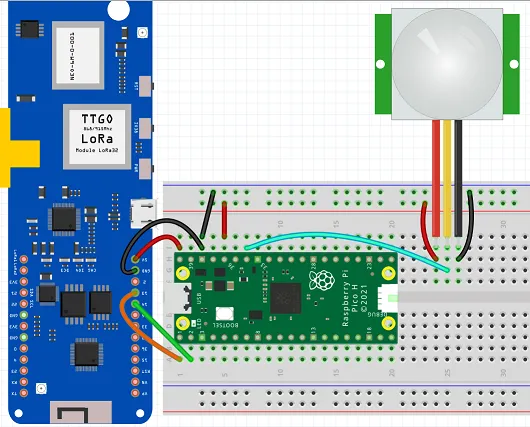
For T1000-E (pogo-pin UART):
- TX pogo pin (P0.16) → RX (GP1) on the Pico
- RX pogo pin (P0.17) → TX (GP0) on the Pico
- GND pogo pin → GND pin 38 on the Pico
For T-Beam V1.1 (GPIO header):
- TX pin 14 on the T-Beam → RX pin 2 on the Pico
- RX pin 13 on the T-Beam → TX pin 1 on the Pico
- GND pin on T-Beam → GND pin 38 on the Pico
PIR sensor connections (both boards):
- PIR Vcc → Pico 3V3 (pin 36)
- PIR GND → Pico GND (pin 38)
- PIR trigger → Pico GPIO28 (pin 34)
CircuitPython Code
import time
import board
import busio
import digitalio

pir = digitalio.DigitalInOut(board.GP28)
pir.direction = digitalio.Direction.INPUT

uart = busio.UART(board.GP0, board.GP1, baudrate=38400, timeout=0)

while True:
    if pir.value:
        uart.write(bytes("Motion Detected\n", "ascii"))
        time.sleep(30)
    time.sleep(0.5)
Arduino Mini Pro BOM
- An Arduino Pro Mini 3.3V/8MHz variant (required for T1000-E — 5V variant outputs 5V on TX which will damage the nRF52840 pogo pins)
- SenseCAP T1000-E (or T-Beam V1.1) running Meshtastic
- PIR Sensor (Adafruit Breadboard Model)
Arduino Mini Pro Wiring
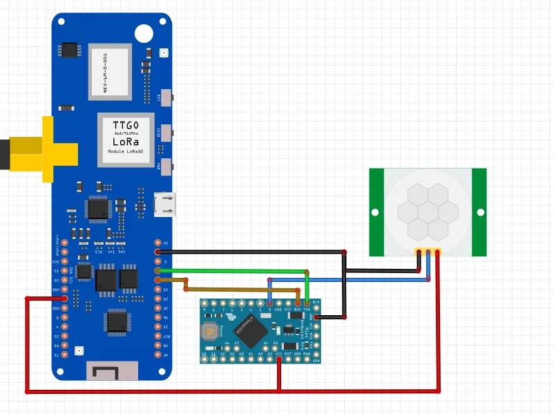
For T1000-E (pogo-pin UART):
- TX pogo pin (P0.16) → RX pin on the Arduino Mini Pro
- RX pogo pin (P0.17) → TX pin on the Arduino Mini Pro
- GND pogo pin → GND on the Arduino Mini Pro
For T-Beam V1.1 (GPIO header):
- T-Beam RX (pin 13) → TX on the Arduino Mini Pro
- T-Beam TX (pin 14) → RX on the Arduino Mini Pro
- T-Beam 3.3V → 3.3V on the Arduino Mini Pro
- T-Beam GND → GND on the Arduino Mini Pro
PIR sensor connections (both boards):
- Arduino Mini Pro pin 2 → PIR OUT
- PIR Vcc → 3.3V rail
- PIR GND → GND rail
Arduino Sketch
const int PIR_PIN = 2;
unsigned long lastTrigger = 0;
const unsigned long DEBOUNCE_MS = 30000;

void setup() {
  Serial.begin(38400);
  pinMode(PIR_PIN, INPUT);
}

void loop() {
  if (digitalRead(PIR_PIN) == HIGH) {
    unsigned long now = millis();
    if (now - lastTrigger > DEBOUNCE_MS) {
      lastTrigger = now;
      Serial.println("Motion Detected");
    }
  }
  delay(500);
}