Telemetry Module Configuration
The Telemetry Module provides four types of data over the mesh: Device metrics (Battery Level, Voltage, Channel Utilization and Airtime) from your Meshtastic device, Environment Metrics, Air Quality Metrics, and Health metrics (Heart rate, Oxygen Saturation and body temperature).
Health telemetry sensor support and configuration options are available only by compiling firmware with the required macros enabled.
Supported sensors connected to the I2CI2CA two-wire bus used to attach peripherals such as sensors and displays to a device. bus of the device will be automatically detected at startup. The Environment Telemetry, Air Quality, and Health Telemetry modules must be enabled for them to be instrumented and their readings sent over the mesh.
Currently Supported Sensor Types
| Sensor | I2C Address | Data Points |
|---|---|---|
| AHT10, AHT20 | 0x38 | Temperature and humidity |
| BMP085 | 0x76, 0x77 | Temperature and barometric pressure |
| BMP180 | 0x76, 0x77 | Temperature and barometric pressure |
| BMP280 | 0x76, 0x77 | Temperature and barometric pressure |
| BME280 | 0x76, 0x77 | Temperature, barometric pressure and humidity |
| BMP388 | 0x76, 0x77 | Barometric pressure, Temperature |
| BMP390 | 0x76, 0x77 | Barometric pressure, Temperature |
| BME68x | 0x76, 0x77 | Temperature, barometric pressure, humidity and air resistance |
| DPS310 | 0x76, 0x77 | Barometric pressure, Temperature |
| MCP9808 | 0x18 | Temperature |
| INA219 | 0x40, 0x41, 0x43 | Current and Voltage |
| INA226 | 0x40, 0x41, 0x43 | Current and Voltage |
| INA260 | 0x40, 0x41, 0x43 | Current and Voltage |
| INA3221 | 0x42 | 3-channel Current and Voltage |
| LPS22 | 0x5D, 0x5C | Barometric pressure |
| SHTC3 | 0x70 | Temperature and humidity |
| SHT31 | 0x44, 0x45 | Temperature and humidity |
| SHT4X | 0x44, 0x45 | Temperature and humidity |
| OPT3001 | 0x44, 0x45 | Light intensity |
| VEML7700 | 0x10 | Light intensity |
| TSL2591 | 0x29 | Light intensity |
| LTR390UV | 0x53 | UV Light intensity |
| RCWL9620 | 0x57 | Ultrasonic Distance Sensor |
| PMSA003I | 0x12 | Concentration units by size and particle counts by size |
| DFROBOT_LARK | 0x42 | Temperature, barometric pressure, humidity, wind direction, wind speed |
| DFROBOT_RAIN | 0x1d | Tip Bucket Rain counter |
| RadSens | 0x66 | Radio Dosimeter |
| MAX30102 | 0x57 | Heart Rate, Oxygen Saturation, and body temperature |
| MLX90614 | 0x5A | Body temperature |
| MLX90632 | 0x3A | Body temperature |
| NAU7802 | 0x2A | 24-Bit differential ADCADC (Analog-to-Digital Converter). A circuit that turns a varying voltage into a digital value. Devices use one to read sensors and to measure battery voltage. for Wheatstone bridge |
| ADS1X15 | 0x48, 0x49, 0x4A, 0x4B | ADCADC (Analog-to-Digital Converter). A circuit that turns a varying voltage into a digital value. Devices use one to read sensors and to measure battery voltage. channel voltages (4 channels per device, 8 with two devices) |
| AS3935 | 0x01, 0x02, 0x03 | Lightning strike count in the past hour and estimated storm distance in km (see AS3935) |
| BH1750 | 0x23 | Light intensity |
| DS18B20 (via DS2482-800/DS2484) | 0x18–0x1F | Temperature (up to 8 1-Wire probes via DS2482-800, 1 via DS2484) |
| HM330X | 0x40 | Concentration units by size |
| MAX17048 | 0x36 | Battery voltage and charge level |
| PCT2075 | 0x37 | Temperature |
| SCD30 | 0x61 | CO2, temperature and humidity |
| SCD4X | 0x62 | CO2, temperature and humidity |
| SEN5X | 0x69 | Particulate matter by size; further metrics vary by model (see SEN5X models) |
| SEN6X | 0x6B | Particulate matter by size; further metrics vary by model (see SEN6X models) |
| SFA30 | 0x5D | Formaldehyde, temperature and humidity |
| SPA06 (Mesh-Tracker-X1 only) | 0x76, 0x77 | Barometric pressure, Temperature |
| TSL2561 | 0x29 | Light intensity |
AS3935
Wire the interrupt (IRQ) pin and define AS3935_IRQ in the variant to avoid an I²CI2CA two-wire bus used to attach peripherals such as sensors and displays to a device. read every second.
SEN5X models
All SEN5X models report particulate matter by size. The SEN50 is the base model, reporting particulate matter only. The SEN54 adds temperature, humidity and VOCVOC (Volatile Organic Compounds). A group of gases measured by some air quality sensors, which report them as an index rather than a concentration. index. The SEN55 adds temperature, humidity, VOCVOC (Volatile Organic Compounds). A group of gases measured by some air quality sensors, which report them as an index rather than a concentration. index and NOxNOx (Nitrogen Oxides). A group of gases measured by some air quality sensors, which report them as an index rather than a concentration. index.
SEN6X models
All SEN6X models report particulate matter by size, temperature and humidity. The SEN62 is the base model, reporting no further metrics. The SEN63C adds CO2. The SEN65 adds VOCVOC (Volatile Organic Compounds). A group of gases measured by some air quality sensors, which report them as an index rather than a concentration. and NOxNOx (Nitrogen Oxides). A group of gases measured by some air quality sensors, which report them as an index rather than a concentration. index. The SEN66 adds VOCVOC (Volatile Organic Compounds). A group of gases measured by some air quality sensors, which report them as an index rather than a concentration. and NOxNOx (Nitrogen Oxides). A group of gases measured by some air quality sensors, which report them as an index rather than a concentration. index and CO2. The SEN68 adds VOCVOC (Volatile Organic Compounds). A group of gases measured by some air quality sensors, which report them as an index rather than a concentration. and NOxNOx (Nitrogen Oxides). A group of gases measured by some air quality sensors, which report them as an index rather than a concentration. index and formaldehyde. The SEN69C adds VOCVOC (Volatile Organic Compounds). A group of gases measured by some air quality sensors, which report them as an index rather than a concentration. and NOxNOx (Nitrogen Oxides). A group of gases measured by some air quality sensors, which report them as an index rather than a concentration. index, CO2 and formaldehyde.
Module Config Values
Environment Telemetry Enabled
Enable the Environment Telemetry (Sensors).
Environment Metrics Update Interval
How often we should send Environment(Sensor) Metrics over the mesh.
Default is 1800 seconds (30 minutes).
Health telemetry options are available only when compiling firmware with the required macros enabled.
Device Metrics Update Interval
How often we should send Device Metrics over the mesh.
Default is 1800 seconds (30 minutes).
Device Metrics to a connected client app will always be sent once per minute, regardless of this setting.
Environment Screen Enabled
Show the environment telemetry data on the device display.
Default is false.
Display Fahrenheit
The sensor is always read in Celsius, but the user can opt to display in Fahrenheit (on the device display only) using this setting.
Default is false.
Air Quality Enabled
This option is used to enable/disable the sending of air quality metrics from an attached supported sensor over the mesh network.
Default is false.
Air Quality Interval
This option is used to configure the interval (in seconds) that should be used to send air quality metrics from an attached supported sensor over the mesh network.
Default is 1800 seconds (30 minutes).
Power Metrics Enabled
This option is used to enable/disable the sending of power telemetry as gathered by an attached supported voltage/current sensor. Note that this does not need to be enabled to monitor the voltage of the battery.
Default is false.
Power Metrics Interval
This option is used to configure the interval (in seconds) that should be used to send power metrics from an attached supported sensor over the mesh network.
Health Telemetry Enabled
This option is used to enable/disable the sending of health data from an attached supported sensor over the mesh network.
Default is false.
Health Telemetry Interval
This option is used to configure the interval (in seconds) that should be used to send health data from an attached supported sensor over the mesh network.
Default is 1800 seconds (30 minutes).
Telemetry Config Client Availability
- Android
- Apple
- CLI
- Web
Android
Telemetry Config options are available for Android.
- Open the Meshtastic App
- Navigate to: Settings > Telemetry
Apple
All telemetry module config options are available on iOS, iPadOS and macOS at Settings > Module Configuration > Telemetry (Sensors).
CLI
All telemetry module config options are available in the python CLI. Example commands are below:
Settings
| Setting | Acceptable Values | Default |
|---|---|---|
| telemetry.device_telemetry_enabled | true, false | false |
| telemetry.device_update_interval | integer (seconds) | Default 0 is 30 minutes(1800 seconds). |
| telemetry.environment_display_fahrenheit | true, false | false |
| telemetry.environment_measurement_enabled | true, false | false |
| telemetry.environment_screen_enabled | true, false | false |
| telemetry.environment_update_interval | integer (seconds) | Default 0 is 30 minutes(1800 seconds). |
| telemetry.air_quality_enabled | true, false | false |
| telemetry.air_quality_interval | integer (seconds) | Default 0 is 30 minutes(1800 seconds). |
| telemetry.power_measurement_enabled | true, false | false |
| telemetry.power_update_interval | integer (seconds) | Default 0 is 30 minutes(1800 seconds). |
| telemetry.health_measurement_enabled | true, false | false |
| telemetry.health_update_interval | integer (seconds) | Default 0 is 30 minutes(1800 seconds). |
| telemetry.health_screen_enabled | true, false | false |
Because the device will reboot after each command is sent via CLI, it is recommended when setting multiple values in a config section that commands be chained together as one.
meshtastic --set telemetry.device_update_interval 0 --set telemetry.environment_update_interval 0
meshtastic --set telemetry.device_update_interval 0
// Device Metrics Two Minutes
meshtastic --set telemetry.device_update_interval 0
// Environment Metrics Two Minutes
meshtastic --set telemetry.environment_update_interval 120
meshtastic --set telemetry.environment_measurement_enabled true
meshtastic --set telemetry.environment_measurement_enabled false
meshtastic --set telemetry.environment_screen_enabled true
meshtastic --set telemetry.environment_screen_enabled false
meshtastic --set telemetry.environment_display_fahrenheit true
meshtastic --set telemetry.environment_display_fahrenheit false
Web
All telemetry module config options are available in the Web UI.
Examples
RAK 4631 with BME680 Environment Sensor
Setup of a RAK 4631 with Environment Sensor
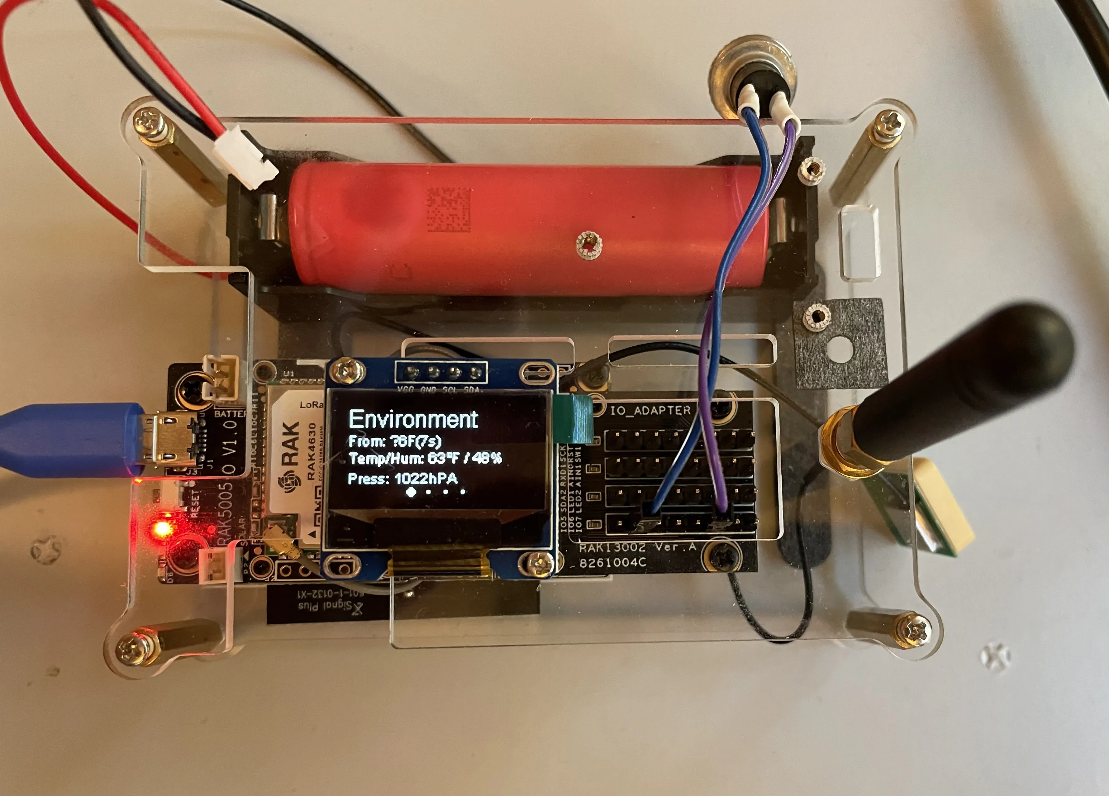
Requirements:
- RAK4631
- Environment Sensor
Steps:
- configure the device:
meshtastic --set telemetry.environment_measurement_enabled true --set telemetry.environment_screen_enabled true --set telemetry.environment_display_fahrenheit true
While the above values serve as an example and can be modified to fit your specific needs, it is advisable to chain multiple commands together, as demonstrated in the example. This approach will minimize the number of necessary reboots.
- Device will reboot after command is sent.
- When the device boots again it should say "Telemetry" and it may show the sensor data
- If this does not appear to have any effects, run:
meshtastic --noproto
And examine the serial logs for Telemetry diagnostic information.
Supporting Additional Sensors
Environment Metrics
The environment metrics in the telemetry module supports a limited amount of fields as they are stored in memory on the device. Support for sensors that provide one or more of the following fields can potentially be added to the main firmware provided there is a GPL licensed library for us to include to support it, and the library size is not prohibitive.
- Temperature
- Relative Humidity
- Barometric Pressure
- Gas Resistance (AQI)
- Voltage
- Current
Supporting Other Sensor types
For other interesting sensor types and use cases we need to add a portnum for more generic telemetry packets and a second MCUMCU (Microcontroller Unit). The microcontroller that runs the firmware on a device. The hardware tables list the MCU for each supported board. will be required to interact with the sensor and process the data to be sent over the mesh. This data will not be stored in the nodedb on the device.