Remote Hardware Module Usage
The Remote Hardware Module allows to read, write and watch GPIO pins on a remote node. Config options are: Enabled.
For firmware versions > 2.5.3, this module requires you to compile your own firmware and remove the -DMESHTASTIC_EXCLUDE_REMOTEHARDWARE=1 build flag in platformio.ini.
Additionally, while configuring this module may be available in clients, setting and reading GPIO's is currently only possible using the Meshtastic Python CLI
Remote Hardware Config Values
Enabled
Whether the module is enabled.
Remote Hardware Module Client Availability
- Android
- Apple
- CLI
- Web
Android
All Remote Hardware Module config options are available for Android in app.
- Open the Meshtastic App
- Navigate to: Settings > Remote Hardware
Apple
All Remote Hardware Module config options are available on iOS, iPadOS and macOS app.and higher at Settings > Module Configuration > Remote Hardware
CLI
All Remote Hardware Module config options are available in the python CLI.
Web
Not implemented.
Remote Hardware Module Usage
GPIO access is fundamentally dangerous because invalid options can physically damage or destroy your hardware. Ensure that you fully understand the schematic for your particular device before trying this as we do not offer a warranty. Use at your own risk.
Supported Operations
- Set any GPIO
- Read any GPIO
- Receive a notification over the mesh if any GPIO changes state. Note that it cannot detect fast changes like button presses. For this, look at the Detection Sensor module instead.
The result of reading a GPIO or notifications of GPIO changes will also be sent over MQTT (if enabled) in JSON format (if enabled).
Setup
You can get the latest python tool/library with pip3 install --upgrade meshtastic on Windows/Linux/OS-X. See the python section for more details.
To prevent access from untrusted users, you must first make a gpio channel that is used for authenticated access to this feature. You'll need to install this channel on both the local and remote node. Furthermore, you need to enable the module on both units.
The procedure using the python command line tool is:
- Connect local device via USB
- Enable the Remote Hardware module:
meshtastic --set remote_hardware.enabled true - Create a GPIO channel:
meshtastic --ch-add gpio - Check the channel has been created and copy the long "Complete URL" that contains all the channels on that device:
meshtastic --info - Connect the remote device via USB (or use the remote admin feature to reach it through the mesh)
- Enable the Remote Hardware module:
meshtastic --set remote_hardware.enabled true - Set it to join the gpio channel you created:
meshtastic --seturl theurlyoucopiedinstep3
Now both devices should be able to talk over the gpio channel. Send a text message from one to the other to verify. Also run --nodes to verify the second node shows up.
Masks
A mask is used to set the GPIOs to control. For GPIO 1, bit 1 of the mask is set (0x2 in hexadecimal), for GPIO 2, bit 2 of the mask is set (0x4 in hexadecimal), and so on. To determine the appropriate mask for the pin(s) that you want to know, the python program (and output) below might help:
>>> for i in range(1,45):
...     print(f'GPIO:{i} mask:{hex(2**i)}')
...
GPIO:1 mask:0x2
GPIO:2 mask:0x4
GPIO:3 mask:0x8
GPIO:4 mask:0x10
GPIO:5 mask:0x20
GPIO:6 mask:0x40
GPIO:7 mask:0x80
GPIO:8 mask:0x100
GPIO:9 mask:0x200
GPIO:10 mask:0x400
GPIO:11 mask:0x800
GPIO:12 mask:0x1000
GPIO:13 mask:0x2000
GPIO:14 mask:0x4000
GPIO:15 mask:0x8000
GPIO:16 mask:0x10000
GPIO:17 mask:0x20000
GPIO:18 mask:0x40000
GPIO:19 mask:0x80000
GPIO:20 mask:0x100000
GPIO:21 mask:0x200000
GPIO:22 mask:0x400000
GPIO:23 mask:0x800000
GPIO:24 mask:0x1000000
GPIO:25 mask:0x2000000
GPIO:26 mask:0x4000000
GPIO:27 mask:0x8000000
GPIO:28 mask:0x10000000
GPIO:29 mask:0x20000000
GPIO:30 mask:0x40000000
GPIO:31 mask:0x80000000
GPIO:32 mask:0x100000000
GPIO:33 mask:0x200000000
GPIO:34 mask:0x400000000
GPIO:35 mask:0x800000000
GPIO:36 mask:0x1000000000
GPIO:37 mask:0x2000000000
GPIO:38 mask:0x4000000000
GPIO:39 mask:0x8000000000
GPIO:40 mask:0x10000000000
GPIO:41 mask:0x20000000000
GPIO:42 mask:0x40000000000
GPIO:43 mask:0x80000000000
GPIO:44 mask:0x100000000000
Using GPIOs from the Python CLI
You can also control or watch GPIOs of your USB-connected node by setting --dest to the local node's ID. No gpio channel is needed in this case.
Writing a GPIO
meshtastic  --port /dev/ttyUSB0 --gpio-wrb 4 1 --dest 28979058
# Connected to radio
# Writing GPIO mask 0x10 with value 0x10 to !28979058
Reading a GPIO
meshtastic --port /dev/ttyUSB0 --gpio-rd 0x10 --dest 28979058
# Connected to radio
# Reading GPIO mask 0x10 from !28979058
# GPIO read response gpio_value=16
If the mask and the gpio_value match, then the value is "on". If the gpio_value is 0, then the value is "off".
Watching for GPIO Changes
meshtastic --port /dev/ttyUSB0 --gpio-watch 0x10 --dest 28979058
# Connected to radio
# Watching GPIO mask 0x10 from !28979058
# Received RemoteHardware typ=GPIOS_CHANGED, gpio_value=16
# Received RemoteHardware typ=GPIOS_CHANGED, gpio_value=0
# Received RemoteHardware typ=GPIOS_CHANGED, gpio_value=16
# < press ctrl-c to exit >
Testing GPIO Operations
You can programmatically do operations from your own python code by using the Meshtastic RemoteHardwareClient class. See the Python API documentation for more details.
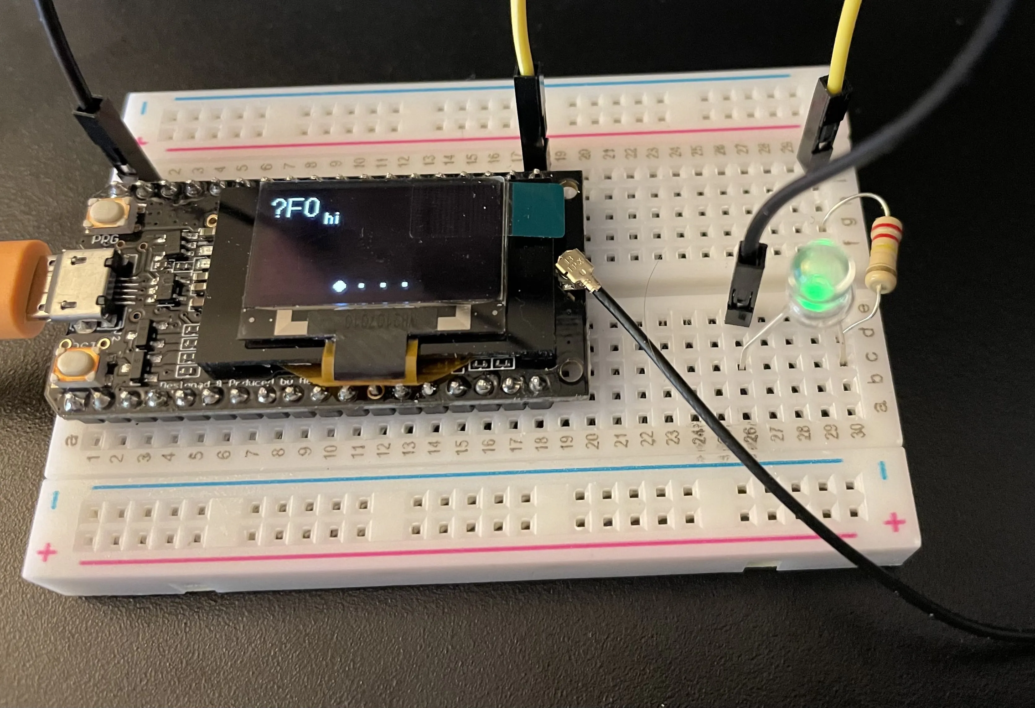
You can add a simple LED and resistor to validate that the GPIO operations work as expected. Use this tutorial as a guide.
Requirements
- (x2) Meshtastic devices (one device could be on a local computer, and the other one just has to be powered and is the one with the LED to be connected to it)
- (x2) wires (black and yellow; they can be any color but typically black is used for ground)
- (x1) LED
- (x1) 220Ω resistor (somewhat optional, but recommended)
- (x1) Breadboard (optional)
Preparation
- Disconnect the remote device from power (battery/usb)
- Connect the resistor to the longer (positive) lead of the LED and the yellow wire to the other end of the resistor
- Connect the other end of the yellow wire to a GPIO pin that will not cause any issues (ex: for TLoraV1, we can use GPIO21)
- Connect the black "ground" wire from the ground pin on the device (ex: for TLoraV1 it is the end pin next to the RST button) to the shorter (negative) lead of the LED
- Power on the device
Validation
By default, the pin may be "off" or "on". (It will most likely "off".) See the steps below for running commands. In the example of GPIO21, the mask would be 0x200000.