Heltec® LoRa 32 Peripherals
- GPS Module
GPS Module
Introduction
This guide outlines the process of enhancing the Heltec ESP32 V3 board by integrating a GT-U7 GPS Module, although almost any supported GNSS module can be integrated in the same way. The addition of this module provides precise GPS capabilities and a real-time clock (RTC), eliminating the need for WiFi or a smartphone for time tracking. This enhancement is particularly beneficial for the mesh, where tracking the duration since the last seen device is crucial.
However, it's important to note that the GPS module increases the power demand of the node. This guide helps to address this by detailing how to incorporate a switch or an N-channel MOSFET into the setup. This enables additional firmware-controlled power management, conserving more battery life than the soft-sleep option without sacrificing functionality.
Benefits
- GPS Capabilities: Provides the node with the ability to determine its location with high precision, which is invaluable for tracking, mapping, and various other applications requiring location data.
- Real-Time Clock (RTC): Ensures accurate timekeeping on the mesh network without relying on external time sources such as the internet or a connected smartphone.
Power Consumption Considerations
The GT-U7 module is known for its high power consumption, which can potentially shorten the battery lifespan of the node. To mitigate this, three approaches are recommended:
- Manual Switch: A simple on/off switch for the GPS module, allowing for manual power management.
- Through-hole MOSFET: Facilitates automatic power control through the firmware, enabling the device to turn off the GPS module based on specific conditions or after a set period.
- SMD MOSFET: As above, but in a smaller volume and space envelope and with a marginally lower power consumption when in use.
Notes on previous versions of these instructions
Previous versions of these instructions specified using a 2N2222a power transistor to control the power. In addition, it showed the transistor being used to control the power from the "high side" (i.e. between the Heltec Vcc and the GPS Vin). While this method will work for some boards, it is not ideal to use an NPN transistor to switch the "high side" of the load like this.
The current version of the guide now instructs using either a surface mount or through-hole MOSFET to switch the ground ("low side") of the GPS module. This allows the MOSFET to operate in the fully saturated condition, and MOSFETs will have a lower power consumption themselves than a power transistor. As the ground for the two parts will now be isolated, it is important that no parts of the GPS module, the antenna or any shielding shell are able to contact the ground for the Heltec board.
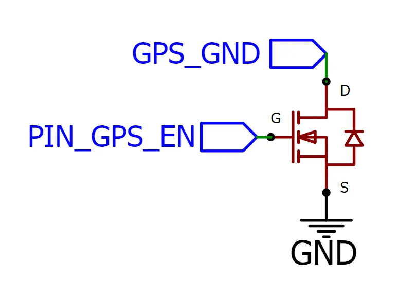
The essential connections for the NPN MOSFET are shown in the schematic below.
Materials Needed
- Heltec ESP32 V3 board
- GT-U7 GPS Module
- (Optional) Through-hole MOSFET (note: these are harder to find in small packages than SMD MOSFETS, but any that can operate on 3.3V will be suitable, e.g. 2N7000, BS170)
- (Optional) Surface Mount MOSFET (note: any suitable N-channel MOSFET can be used, e.g. SI2312, AO3400a, 2N7002)
- Wires and soldering equipment
- (Optional) Switch for manual power control
Instructions (Through-Hole MOSFET)
Note: these instructions assume a 2N7000 MOSFET is used. For other parts, always check the data sheet!
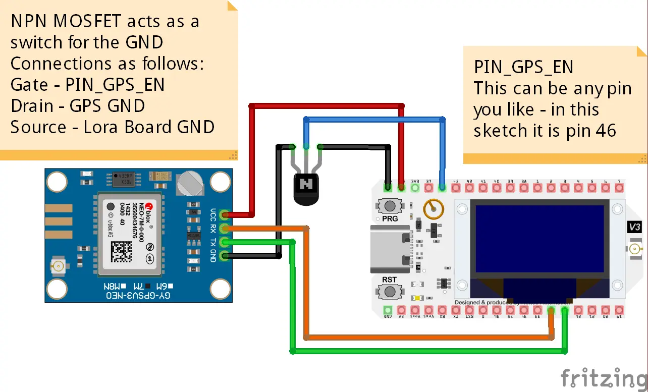
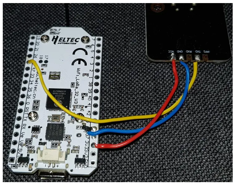
- Solder a wire from the TXD pin on the GPS module to GPIO 48 on Heltec board. (Another GPIO pin may be chosen)
- Solder a wire from the RXD pin on the GPS module to GPIO 47 on Heltec board. (Another GPIO pin may be chosen)
- Solder a wire from the VCC pin on the GPS module to 3V/5V pin on Heltec board.
- Solder a wire from Right leg (lead 3, Drain) of NPN MOSFET to GND on GPS module.
- Solder a wire from Left leg (lead 1, Source) of NPN MOSFET to GND on Heltec board.
- Solder a wire from Middle leg (lead 2, Gate) of NPN MOSFET to GPIO 46 of Heltec board. (Another GPIO pin may be chosen)
- Go to Meshtastic app > Radio Configurations > Position
- Set GPS_RX_PIN to 48 (This will communicate to the TXD pin on the GPS)
- Set GPS_TX_PIN to 47 (This will communicate to the RXD pin on the GPS)
- Set PIN_GPS_EN to 46 (This will allow the meshtastic firmware to turn off the power on the GPS board with the user button of the Heltec Board by pressing it 3 times)
Wiring Diagram - Through-Hole
Instructions (Surface Mount MOSFET)
Note: these instructions assume an SI2312 MOSFET is used. For other parts, always check the data sheet!
- Solder a wire from the TXD pin on the GPS module to GPIO 48 on Heltec board. (Another GPIO pin may be chosen)
- Solder a wire from the RXD pin on the GPS module to GPIO 47 on Heltec board. (Another GPIO pin may be chosen)
- Solder a wire from the GND pin on the GPS module to middle pin of the SI 2312 MOSFET
- Solder a wire from the VCC pin of the GPS module to o 3V/5V pin on Heltec board.
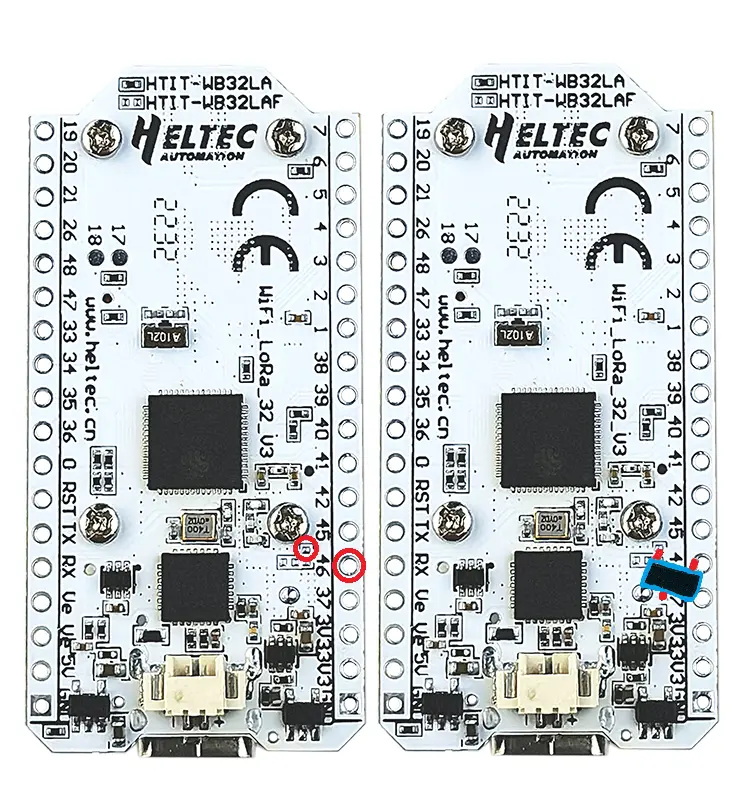
- Solder a wire from Left leg of SI2312 MOSFET to GPIO 46 on the Heltec board.
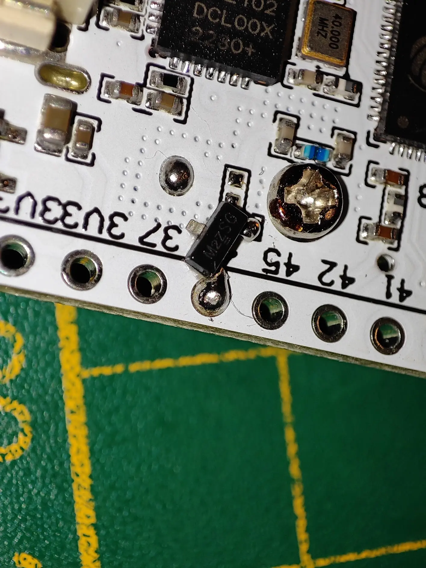
- Solder a wire from Right leg of SI2312 MOSFET to the empty solder spot on the heltec board (see pictures).
- Go to Meshtastic app > Radio Configurations > Position
- Set GPS_RX_PIN to 48 (This will communicate to the TXD pin on the GPS)
- Set GPS_TX_PIN to 47 (This will communicate to the RXD pin on the GPS)
- Set PIN_GPS_EN to 46 (This will allow the meshtastic firmware to turn off the power on the GPS board with the user button of the Heltec Board by pressing it 3 times)
- Ensure that the ground on the GPS module does not contact the ground of the Heltec board, or any other component linked to the Heltec ground. This includes antenna covers, battery connectors, etc. Failure to ensure they are separated may lead to the MOSFET being bypassed.
Photographs and Diagrams - SMD
Troubleshooting Tips
If the GPS module does not power on, check the connections to the transistor and ensure that the middle pin is properly configured in the firmware settings. If the message "GPS is Disabled" appears, press the user button on the Heltec board three times to enable it. If the message "No GPS Present" appears, check that the TXD and RXD are correctly configured. If the message "No GPS Lock" appears, move the node to another location with access to the sky for a bit to lock on properly. If the location is not accurate, walk around to allow the GPS to properly lock on.
Conclusion
By following this guide, the Heltec ESP32 V3 board can be enhanced with valuable GPS capabilities and an RTC, while effectively managing power consumption. Whether for a hobby project or a more serious application, these additions significantly expand the potential of the device.