RAK WisBlock Core Modules
- RAK4631
- RAK11310
- RAK3312
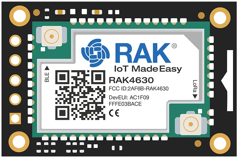
RAK4631 - nRF52
Please be aware of the difference between the RAK4631 (Arduino bootloader) and the RAK4631-R (RUI3 bootloader). Meshtastic requires the Arduino bootloader. If you have a RAK4631-R, please see the instructions for converting the bootloader.
- RAK4631
- MCU
- nRF52840
- Bluetooth BLE 5.0
- Very low power consumption
- nRF52840
- LoRa Transceiver:
- SX1262
- Frequency Options:
- 433 MHz
- 470 MHz
- 799 MHz
- 865 MHz
- 868 MHz
- 915 MHz
- 920 MHz
- 923 MHz
- Connectors:
- U.FL/IPEX antenna connector for LoRa
- MCU
Resources
- Firmware file:
firmware-rak4631-X.X.X.xxxxxxx.uf2 - Further information on the RAK4631 can be found on the RAK Documentation Center.
- Purchase Links:
- US
- International
GPIO
There is no usable GPIO pin on any RAK base board except the 'big' baseboard RAK19001 without adding a RAK13002 IO module or a third party IO sensor breakout.
The RAK4631 uses symbolic labels for its I/O Pins on the module and baseboard silk screens. The following table shows the mapping of the RAK4631 GPIO pins to the corresponding Arduino pins and the MCU Port numbers.
| RAK Pin | nRF52840 Pin | Arduino GPIO | Remark |
|---|---|---|---|
| IO1 | P0.17 | 17 | used to toggle power to peripheral modules using 3v3_S power rail, not available for user application |
| IO2 | P1.02 | 34 | used to power all peripheral modules, not available for user application |
| IO3 | P0.21 | 21 | |
| IO4 | P0.04 | 4 | |
| IO5 | P0.09 | 9 | The 'User Button' is mapped here. |
| IO6 | P0.10 | 10 | |
| IO7 | P0.28 | 28 | |
| SW1 | P0.01 | 1 | |
| A0 | P0.04/AIN2 | A2 | |
| A1 | P0.31/AIN7 | A7 | |
| SPI_CS | P0.26 | 26 |
When configuring GPIO pins in your device settings, the Arduino GPIO numbers should be used.
meshtastic --set external_notification.output 10
This will use IO6 on a RAK4631
RAK11310 - RP2040
Please note, this core module does NOT include BLE/WiFi.
- MCU:
- Raspberry Pi RP2040
- Dual M0+ Core
- 133MHz CPU Clock
- Raspberry Pi RP2040
- LoRa Transceiver:
- SX1262
- Frequency Options:
- 433 MHz
- 470 MHz
- 864 MHz
- 865 MHz
- 868 MHz
- 915 MHz
- 920 MHz
- 923 MHz
- Connectors:
- U.FL/IPEX antenna connector for LoRa
Resources
- Firmware file:
firmware-rak11310-X.X.X.xxxxxxx.uf2 - Further information on the RAK11310 can be found on the RAK Documentation Center.
- Purchase Links:
RAK3312 - ESP32-S3
- MCU:
- ESP32-S3 (WiFi + BLE 5.0)
- Dual LX7 Core
- 240MHz CPU Clock
- 6 MB Flash
- 512 kB SRAM
- 512 kB RAM
- 8 MB PSRAM
- 16 kB RTC SRAM
- ESP32-S3 (WiFi + BLE 5.0)
- LoRa Transceiver:
- SX1262
- Frequency Options:
- 864 MHz
- 865 MHz
- 868 MHz
- 915 MHz
- 920 MHz
- 923 MHz
- Connectors:
- MHF4 IPEX antenna connector for LoRa
- MHF4 IPEX antenna connector for Wifi/BLE
Resources
- Firmware file:
firmware-rak3312-X.X.X.xxxxxxx.bin - Further information on the RAK3312 can be found on the RAK Documentation Center.
- Purchase Links:
- US
- International - RAKwireless Store - HexaSpot