Seeed Wio-E5
- Wio-E5 Dev Kit
- Wio-E5 mini Dev Board
- Wio-E5 Wireless Module
Wio-E5 Dev Kit
- MCU
- STM32WLE5JC
- LoRa Transceiver
- STM32WL integrated sub-GHz radio (Semtech SX126x-based)
- Frequency options
- 868 MHz
- 915 MHz
- 923 MHz
- Connectors
- USB-C
- LoRa Antenna: SMA antenna connector and U.FL/IPEX
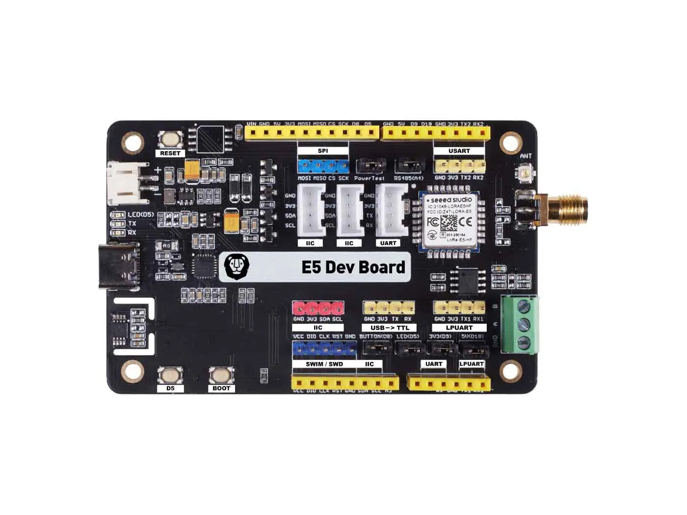
- 2.54 mm breakout header (all 28 module pins)
- 2x Grove I2C (same bus) + 1x Grove UART
- RS-485 screw terminal
- Battery
- SWD header
Features
- Temperature and Humidity Sensor (NXP LM75ADP)
- Reset switch, power jumpers, button
Pinout
| Interface | Pin(s) | Arduino | Grove | 2.54 mm header | Meshtastic wio-e5 |
|---|---|---|---|---|---|
UART (TX / RX) | PB6 / PB7 | ✅ | ✅ | ✅ | Serial console |
USART (TX2 / RX2) | PA2 / PA3 | ✅ | - | ✅ | Serial2 → GPS (shared with RS-485); ROM bootloader USART2 |
LPUART (TX1 / RX1) | PC1 / PC0 | ✅ | - | ✅ | unused |
IIC (SDA / SCL) | PA15 / PB15 | ✅ | ✅ (×2 in parallel) | ✅ | I2C bus (PIN_WIRE_SDA / PIN_WIRE_SCL); onboard LM75 sensor |
SWIM/SWD (DIO / CLK / RST) | PA13 / PA14 / NRST | ✅ | - | ✅ | first flash and debugging |
SPI (MOSI / MISO / CS / SCK) | PA10 / PB14 / PB9 / PB13 | ✅ | - | ✅ | unused |
BOOT button | PB13 | ✅ | - | ✅ | unused |
D5 | PB5 | ✅ | - | - | LED_POWER (active low; jumper J16) |
D0 | PA0 | ✅ | - | - | unused (button; jumper J14) |
D9 | PA9 | ✅ | - | - | unused (3V3 peripheral-rail enable; jumper J15) |
D10 | PB10 | ✅ | - | - | unused (5V rail enable; jumper J6) |
A4 | PB4 | ✅ | - | - | unused (RS-485 driver enable; jumper J17) |
| GPIO / ADC | PB3 | ✅ | - | - | unused |
Connecting a GPS
Meshtastic looks for a GPS module on Serial2 (USART2, PA2 / PA3). Connect a supported TTL-level serial GPS to the USART pins (TX2/RX2) on either the 4-pin USART header or the Arduino socket.
If using a Grove GPS module, do not connect it to the Grove UART connector as it is connected in hardware to the same USART port of the USB-C serial converter, which is used for the Meshtastic serial console and wired client link. Instead, connect the Grove GPS module to the male 2.54mm header instead (the pinout is the same, but check the polarity is correct before connecting).
Ensure the jumper labelled RS485(A4) is open to avoid the RS-485 driver coming online on the same USART.
Flashing
- Flashing over SWD
- Flashing over UART — needs an external USB-TTL serial adapter unless the USB-C workaround below is used
Flashing over USB-C
The STM32WL bootloader does not support the pins that the USB-C serial converter is wired to, so this workaround must be used:
- Rebooting the Wio-E5 into bootloader from the Meshtastic client (or
meshtastic --enter-dfu) - Make these temporary connections:
UARTTX↔USARTTX2UARTRX↔USARTRX2
- Flash over UART
- Remove the temporary connections (to prevent the GPS probing from interfering with USB console/client connections)
Resources
Wio-E5 mini Dev Board
- MCU
- STM32WLE5JC
- LoRa Transceiver
- STM32WL integrated sub-GHz radio (Semtech SX126x-based)
- Frequency options
- 868 MHz
- 915 MHz
- 923 MHz
- Connectors
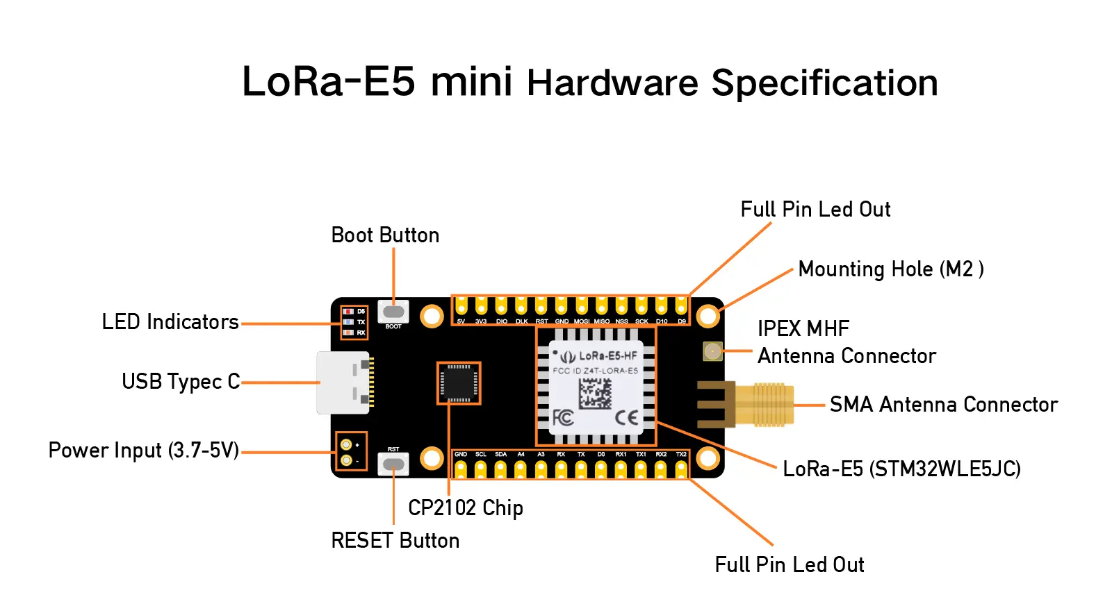
- USB-C
- LoRa Antenna: SMA antenna connector and U.FL/IPEX
- 2x14 castellated/through-hole header (all 28 module pins)
Features
- Reset switch, power jumpers, button
Pinout
The mini breaks out all 28 module pins on a 2x14 castellated/through-hole header with no onboard peripherals other than the USB-C serial bridge (USART1, PB6 / PB7), the active-low user LED (PB5), and the active-low BOOT and D0 buttons (PB13 GPIO — not BOOT0 — and PA0). The LoRa RF pin (RFIO) goes to the SMA and U.FL/IPEX connectors.
The Meshtastic wio-e5 pin assignment is the same as the bare module — see the Wio-E5 Wireless Module pinout.
Flashing
- Flashing over SWD
- Flashing over UART — needs an external USB-TTL serial adapter unless the USB-C workaround below is used
Flashing over USB-C
The STM32WL bootloader does not support the pins that the USB-C serial converter is wired to, so this workaround must be used:
- Rebooting the Wio-E5 into bootloader from the Meshtastic client (or
meshtastic --enter-dfu) - Make these temporary connections:
UARTTX↔USARTTX2UARTRX↔USARTRX2
- Flash over UART
- Remove the temporary connections (to prevent the GPS probing from interfering with USB console/client connections)
Resources
Wio-E5 Wireless Module
- MCU
- STM32WLE5JC
- LoRa Transceiver
- STM32WL integrated sub-GHz radio (Semtech SX126x-based)
- Frequency options
- 868 MHz
- 915 MHz
- 923 MHz
The Wio-E5 is a 12 x 12 mm castellated SMD module for embedding an STM32WL node into a product. It is sold as the Wio-E5-HF (up to 22 dBm) and Wio-E5-LE (up to 14 dBm), and exposes UART, I2C, SPI, ADC, GPIO and SWD. BOOT0 is not brought out (pin 24 BOOT is an ordinary GPIO). The ROM bootloader's UART pins are USART1 on module pins 21 (PA9, TX) / 27 (PA10, RX) and USART2 on pins 19 (PA2, TX) / 18 (PA3, RX); route one pair to the host for UART flashing.
Features
- Integrated 32.768 kHz and 32 MHz crystals
- Single RF I/O (RFIO) pin
Pinout
Every Wio-E5 board (module, mini, Dev Kit) runs the single Meshtastic wio-e5 variant, so the STM32WLE5JC pin assignment below is the same on all of them. The middle column is the raw STM32WL function; each board wires connectors, buttons and LEDs to these pins differently.
| STM32WLE5JC pin | STM32WL function | Meshtastic wio-e5 |
|---|---|---|
| PB6 / PB7 | USART1 TX / RX | Serial console (not a bootloader UART) |
| PA15 / PB15 | I2C2 SDA / SCL | I2C bus (PIN_WIRE_SDA / PIN_WIRE_SCL) |
| PA2 / PA3 | USART2 TX / RX | Serial2 → GPS; ROM bootloader USART2 |
| PC1 / PC0 | LPUART1 TX / RX | unused |
| PB5 | GPIO (boards wire an active-low LED) | LED_POWER |
| PA13 / PA14 | SWDIO / SWCLK | first flash and debugging |
| PB13 | GPIO / SPI2 SCK — not BOOT0 | unused |
| PA0 | GPIO (boards wire an active-low button) | unused |
| RFIO | LoRa RF | LoRa antenna |
| NRST | Reset | — |
Remaining pins (PB3/PB4, PB9/PB14/PA10 SPI2, PB10, PA9, PB0) are broken out but unused by the firmware.
Flashing
Resources
BOOT0 is not exposed on any Wio-E5 board (module, mini, or Dev Kit — the BOOT button is an ordinary GPIOGPIO (General Purpose Input/Output). An uncommitted digital signal pin on a device., not BOOT0), so the first flash of Meshtastic firmware requires an SWDSWD (Serial Wire Debug). A two-pin debug and programming interface, used on STM32 devices to enter bootloader mode and flash firmware. programmer. Meshtastic clients can reboot the board into the bootloader (meshtastic --enter-dfu) once Meshtastic firmware has been flashed.
Wio-E5 boards also ship with flash readout protection (RDP level 1) enabled. If STM32CubeProgrammer cannot read or write flash, see Removing readout protection.